Here’s the hardware block diagram for the Bispectrum Visualizer, which shows the “big picture” approach to the hardware implementation.
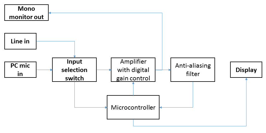
Let’s start with the external facing subcomponents (in boldface). The device will have two audio input connectors: one for a microphone, and another for a line-level audio source. This will allow the system to display the bispectrum of live sounds in the environment, or from a pre-recorded source, such as a personal music player. A switch will be used to define which input source (microphone or line in) is used to compute the bispectrum. A mono monitor out is provided so that inputs may be optionally monitored or recorded by an external device. A display is included, of course, to display the bispectrum.
The most important internal analog subcomponents are the amplifier and anti-aliasing filter. The gain of the amplifier will be controlled by the microcontroller at minimum according to which input is selected, and perhaps also according to whether clipping is detected in the digitized audio stream. The anti-aliasing filter prevents frequencies above the Nyquist frequency from being “reflected” (or aliased) to lower frequencies, corrupting the signal at the frequencies of interest. And finally, the microcontroller will contain the analog-to-digital converter, memory, and signal processing firmware to compute the bispectrum and send it to the display.